Session: Polygon
SMTK has a session type named polygon that sessions Boost.polygon’s modeling kernel. This kernel provides access to 2-D polygonal models, with operators that allow model edges and faces to be split or merged as well as boolean operations and Voronoi diagram computation.
Boost’s polygonal modeler uses integer arithmetic to achieve high performance with robust geometric predicates. SMTK converts 3-D floating-point coordinates into 2-D integer coordinates for you, but you must provide several pieces of information for each model instance:
A base point for the plane holding the polygon
Either x- and y-axis vectors (in 3-D world coordinates) describing the planar coordinate system you wish to use, or an x-axis and the plane’s normal vector.
Either a minimum feature size (in world coordinates) that your model should represent or an integer model scaling factor that each world coordinate is multiplied by before rounding to an integer.
This session does not allow model edges to have more than 2 model vertices. A model edge may have zero or one vertices when the edge is a periodic loop denoted with identical first and last points; in this case, the first and last point must also be the model vertex. A model edge must have two model vertices when it is not periodic, one at each end of the edge. Model edges may have any number of interior points that are not model vertices. These restrictions are imposed so that it is possible to quickly determine what model face lies adjacent to each model vertex. If model edges could have interior vertices, the assumption that each edge may border at most 2 faces would be much more difficult to enforce and validate.
This decision regarding model vertices and edges has further implications. Edges may not have any self-intersections other than at points where segments meet. When edges are joined into loops to form a face, they are intersected with one another first; if any intersections are found, then the model edges are split when the face is created.
Note that SMTK is slightly more restrictive (in that it splits edges and creates model vertices) than Boost requires because Boost does not model edges at all; instead it models polygons as sequences of points – optionally with a list of holes which are themselves polygons. In Boost’s modeler, points are not shared between faces; each face is a model in its own right. Because of this, it is simple for Boost to use keyholed edges to represent holes in faces. Keyholed edges are edges coincident along a portion of their length and effectively split a face with holes into a face with no holes but with infinitesimal slivers connecting the region outside the face to each hole. SMTK can accept keyholed edges but they must be broken into multiple model edges at intersections so that SMTK’s assumption that planar edges border at most 2 different surface regions.
Meshing Boost.polygon models
Boost polygonal models are conforming piecewise-linear cell complexes (PLCs), and may thus be meshed by any SMTK mesh worker that accepts models in this form.
PPG File Format
The SMTK polygon session includes an ImportPPG operation for creating 2-D
models from text file input. The ImportPPG operation is provided as a
convenience for exploring CMB’s many capabilities as well as for testing,
debug, and demonstration.
The “ppg” (Planar PolyGon) file format is a simple data format
that specifies 2-D geometry as a list of vertex coordinates and
polygon face definitions, with vertices connected implicitly by
straight-line model edges.
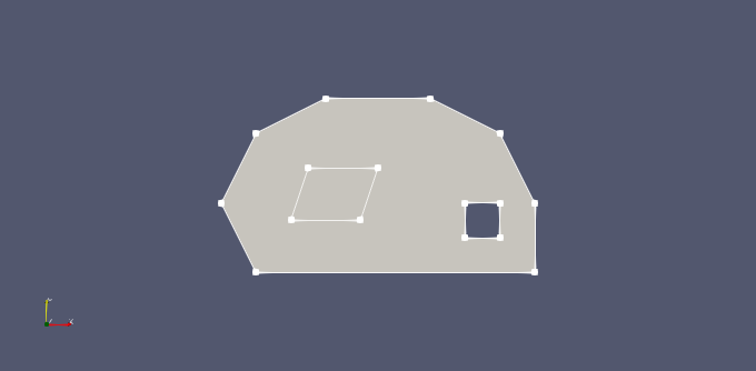
# example1.ppg
# Polygon domain with embedded face and hole
# Note that vertex indices start with 1
# Vertices 1-8 for the outer polygon
v  0.0  2.0
v  1.0  0.0
v  9.0  0.0
v  9.0  2.0
v  8.0  4.0
v  6.0  5.0
v  3.0  5.0
v  1.0  4.0
# Vertices 9-12 for the embedded parallelogram
v 2.0 1.5
v 4.0 1.5
v 4.5 3.0
v 2.5 3.0
# Vertices 12-16 for the square hole
v  7.0  1.0
v  8.0  1.0
v  8.0  2.0
v  7.0  2.0
# Faces
f 1 2 3 4 5 6 7 8  # face 1
e 9 10 11 12       # face 2 (embedded)
h 13 14 15 16      # hole
This example produces a model with two faces, a parallelogram-shaped face embedded in a polygon face that also contains a square hole.
PPG Features
As a tool intended mainly for educational use, the supported feature set is purposely limited.
Each polygon face must have simple geomety, specifically, polygons cannot be self-intersecting, and polygons with more than four edges must be convex.
Polygons may share edges but cannot otherwise intersect or overlap.
Polygons may include inner edge loops as either holes or embedded faces. Inner edge loops may not share edges or vertices with other loops, and embedded faces may not contain inner edge loops themselves.
The ImportPPG operation has only syntactic checking, so users are encouraged to check their input files carefully for geometric validity.
File Format
A PPG file may contain comments, vertex data, and face elements. Empty lines are ignored.
Comments
Anything following a hash character (#) is a comment.
Vertices
A model vertex is specified via a line starting with the letter
v followed by the x and y coordinates.
Face Elements
Model faces are specified using a list of vertex indices. Vertex indices start with 1. Each face is defined by three or more vertices.
An model face is specified with the letter
ffollowed by an ordered list of vertex indices. ImportPPG will create a model edge between each pair of adjacent vertices in the list, and between the last and first vertices, to form a polygon.Inner edge loops can be specified in the lines immediately following the model face.
Embedded faces are specified with the letter
efollowed by an ordered list of vertices.Holes in the model face are specified with the letter
hfollowed by an ordered list of vertices.
Shared Edges
As noted above, model faces can be adjacent with a common internal edge between them. Note that the vertices at either end of the common edge must be included in the vertex list of each face.
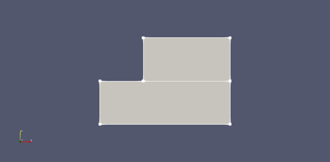
# example2.ppg
# Two adjacent faces with common edge
v 0 0
v 3 0
v 3 1
v 1 1
v 0 1
v 3 2
v 1 2
f 1 2 3 4 5    # face 1
f 3 6 7 4      # face 2